Computer Networks
OSI (Open System Interconnection)
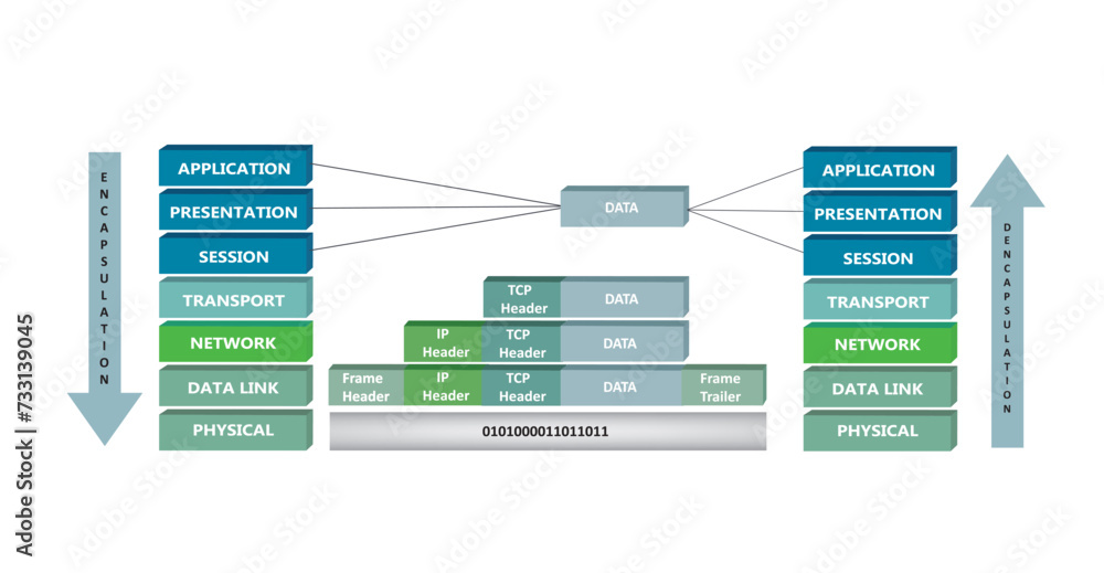
ISO (International Standard Organization) developed a referenced model for networks design in 1997 commonly known as OSI. It proposed a seven-layer architecture for networks, which describe how the information from a software application in a computer move through a network medium to a software application in another computer.
1. Physical Layer
The Physical Layer is the foundation of the OSI model, focusing on the transmission of raw binary data (bits) over a physical medium.
It defines the hardware specifications and how data is encoded into electrical, optical, or radio signals for transmission.
This layer handles aspects like voltage levels, timing, and the physical connectors.
Devices like network cables, fiber optics, hubs, and repeaters operate at this level.
2. Data Link Layer
The Data Link Layer ensures reliable data transfer over the physical link by organizing raw data into structured frames and handling error detection and correction. This layer handles node-node communication. This layer has two sublayers:
Logical Link Control (LLC): Manages error detection and flow control.
Media Access Control (MAC): Governs how devices on a shared network medium (like Ethernet) access the channel.
It uses MAC addresses to uniquely identify devices on a network. Protocols like Ethernet (IEEE 802.3) and Wi-Fi (IEEE 802.11) operate here, as do devices like switches and bridges.
3. Network Layer
The Network Layer focuses on routing and logical addressing, enabling data to move across multiple interconnected networks.
It enables host to host communication.
It uses IP addresses (IPv4 or IPv6) to identify devices and determine the best path for data to travel.
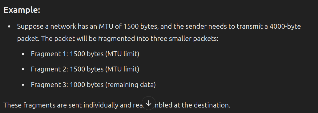
This layer also handles packet fragmentation and reassembly to accommodate the maximum transmission unit (MTU) of the underlying networks.
Devices like routers operate here, ensuring that a data packet originating from one network reaches its destination on another network, even if intermediate networks use different technologies.
4. Transport Layer
The Transport Layer ensures end-to-end communication reliability between devices. It manages segmentation & reassembly of data, error detection and correction, and flow control to prevent overwhelming the receiver.
Two primary protocols operate at this layer:
TCP (Transmission Control Protocol): Ensures reliable, ordered delivery of data. It establishes a connection, monitors the transfer, and retransmits lost data if necessary. TCP is used for applications like web browsing (HTTP) and email (SMTP).
UDP (User Datagram Protocol): Offers faster, connectionless communication without guarantees of reliability. It’s ideal for applications like video streaming or online gaming, where speed is critical.
For example, when you watch a live stream, UDP transmits the video and audio data without waiting for acknowledgments, ensuring minimal delay.
5. Session Layer
The Session Layer establishes, maintains, and terminates communication sessions between devices. Following are the services provided by this layer:
Dialog Control: Manages communication between devices to determine whose turn it is to transmit data.
Token Management: Uses mechanisms like tokens to prevent simultaneous access to critical resources, ensuring orderly communication.
Synchronization: Handles synchronization by creating checkpoints in a data stream. If there’s a failure, communication can resume from the last checkpoint instead of starting over.
6. Presentation Layer
The Presentation Layer serves as a translator, converting data between application-layer formats and network-compatible forms.
It handles tasks like data compression to reduce size, encryption to secure communication, and formatting conversions (e.g., from text to ASCII).
For example, when transmitting an encrypted email, this layer encrypts the content before sending it and decrypts it upon receipt.
7. Application Layer
The Application Layer is where users interact with the network through software applications.
It provides network services directly to end-users, enabling functions like file transfers, email, and web browsing.
Common protocols include:
HTTP/HTTPS: For accessing web pages.
SMTP: For sending emails.
DNS: For resolving domain names to IP addresses.
FTP/SFTP: For transferring files.
For instance, when a user types a URL in a browser, the browser communicates with web servers via the HTTP protocol to retrieve and display the requested webpage.
TCP/IP model

The TCP/IP (Transmission Control Protocol/Internet Protocol) model is a streamlined, practical framework for understanding how data is transmitted over the internet and other networks.
Unlike the OSI model, the TCP/IP model has four layers, each responsible for a set of related functions.
This model is widely used because it directly corresponds to real-world protocols and technologies.
1. Network Interface Layer (Link Layer)
The Network Interface Layer, also known as the Link Layer, is responsible for handling communication between the physical hardware and the network.
This layer combines elements of the OSI model's Physical and Data Link layers.
It ensures that data is transmitted over the physical medium, such as Ethernet, Wi-Fi, or other technologies, using protocols that define how devices interact within a local network.
It deals with tasks like framing, addressing (using MAC addresses), and error detection within the same network.
For example, when two devices on a local Ethernet network communicate, this layer ensures that the data is framed and delivered correctly.
2. Internet Layer
The Internet Layer is the backbone of the TCP/IP model & corresponds closely to the Network Layer in the OSI model.
The Internet Layer focuses on routing and logical addressing, enabling data to move across multiple interconnected networks.
It uses IP addresses (IPv4 or IPv6) to uniquely identify devices and finds best path for data to travel.
It employs protocols like IP for packet delivery, ICMP (Internet Control Message Protocol) for diagnostics (e.g., ping), and ARP (Address Resolution Protocol) for resolving IP addresses to MAC addresses.
This layer also handles packet fragmentation and reassembly to accommodate the maximum transmission unit (MTU) of the underlying networks.
Devices like routers operate here, ensuring that a data packet originating from one network reaches its destination on another network, even if intermediate networks use different technologies.
3. Transport Layer
The Transport Layer ensures end-to-end communication reliability between devices. It manages segmentation of data into smaller packets, error detection and correction, and flow control to prevent overwhelming the receiver. Two primary protocols operate at this layer:
TCP (Transmission Control Protocol): Ensures reliable, ordered delivery of data. It establishes a connection, monitors the transfer, and retransmits lost data if necessary. TCP is used for applications like web browsing (HTTP) and email (SMTP).
UDP (User Datagram Protocol): Offers faster, connectionless communication without guarantees of reliability. It’s ideal for applications like video streaming or online gaming, where speed is critical.
For example, when you watch a live stream, UDP transmits the video and audio data without waiting for acknowledgments, ensuring minimal delay.
4. Application Layer
The Application Layer in the TCP/IP model combines the roles of the OSI model’s Application, Presentation, and Session layers. The Application Layer is where users interact with the network through software applications. It provides network services directly to end-users, enabling functions like file transfers, email, and web browsing.
Key Functions:
Data Translation: Converts data between application formats (like text or multimedia) and network-compatible forms.
Communication Management: Initiates and terminates interactions between software applications on different devices.
Common protocols include:
HTTP/HTTPS: For accessing web pages.
SMTP: For sending emails.
DNS: For resolving domain names to IP addresses.
FTP/SFTP: For transferring files.
For instance, when a user types a URL in a browser, the browser communicates with web servers via the HTTP protocol to retrieve and display the requested webpage.
OSI and TCP/IP model (6 points)
| OSI Model | TCP/IP Model |
| Developed by ISO as a theoretical framework. | Developed by DARPA for practical implementation of the internet. |
| Has 7 layers: Physical, Data Link, Network, Transport, Session, Presentation, Application. | Has 4 layers: Network Interface, Internet, Transport, Application. |
| Focuses on defining a standard framework for networking. | Focuses on standardizing protocols for internet communication. |
| Protocol-agnostic, provides a guideline for protocol development. | Includes specific protocols like TCP, IP, UDP, HTTP, FTP, etc. |
| Theoretical; rarely used in real-world applications as-is. | Practical; forms the backbone of internet communication today. |
| More detailed and comprehensive with seven layers. | Simpler and more streamlined with four layers. |
Protocol Stack
Protocol: A protocol is a set of rules and conventions that define how devices communicate with each other. It ensures that data is transmitted, received, and understood correctly across a network, regardless of the underlying hardware or software.
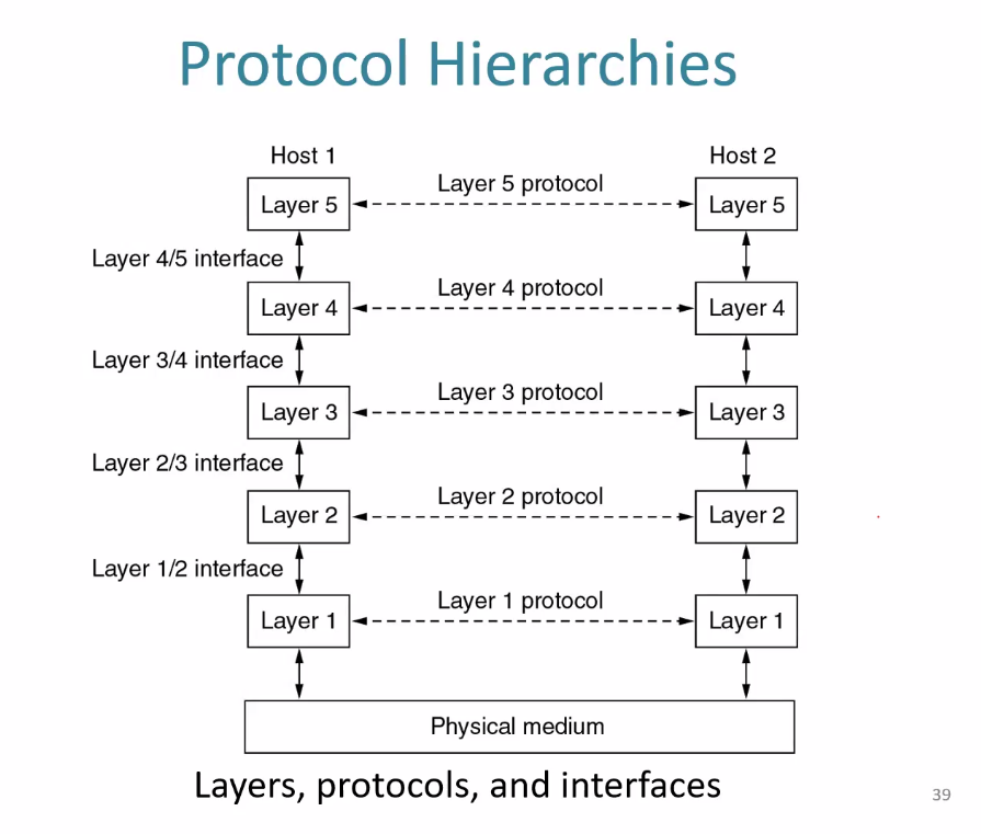
The protocol stack is the hierarchical arrangement of protocols that work together to enable communication in a networked environment. It provides a structured approach for designing network communication systems, dividing tasks into layers where each layer has a specific role and communicates with adjacent layers.
Components of a Protocol Stack:
Layered Design:
A protocol stack is organized in layers, with each layer handling specific responsibilities.
Common models include the TCP/IP stack (4 layers) and the OSI model (7 layers).
Encapsulation:
Data moves down the stack on the sender side, with each layer adding its own header (and sometimes footer).
At the receiving side, the stack decapsulates the data as it moves upward, removing headers and reconstructing the original message.
Layer Interaction:
Each layer uses the services of the layer directly below it and provides services to the layer above it.
This modular approach simplifies network design, debugging, and scalability.
Benefits of a Protocol Stack:
Interoperability: Devices from different vendors can communicate if they follow standard protocols (e.g., HTTP, TCP/IP).
Modularity: Changes in one layer do not impact others significantly.
Ease of Understanding: Complex processes are broken into manageable parts.
TCP vs. UDP (8 points)
| TCP (Transmission Control Protocol) | UDP (User Datagram Protocol) |
| Connection-oriented; requires a handshake to establish a connection. | Connectionless; no handshake; data is sent directly. |
| Reliable; ensures delivery using acknowledgments, retransmissions, and error checking. | Unreliable; does not guarantee the delivery. |
| Slower due to connection setup, acknowledgments, and retransmissions. | Faster as it has minimal overhead and no connection setup. |
| Ensures data is delivered in the correct order. | Does not guarantee order; data may arrive out of sequence. |
| Larger header size (20 bytes or more) due to features like sequence numbers and acknowledgments. | Smaller header size (8 bytes) as it lacks extra features like sequencing. |
| Provides flow control to manage data transmission rates between sender and receiver. | No flow control; sender transmits data at its own rate. |
| Suitable for applications like file transfer, email, and web browsing, where reliability is critical. | Suitable for applications like video streaming, VoIP, and gaming, where speed and low latency are priorities. |
| Examples include HTTP, HTTPS, FTP, SMTP, Telnet. | Examples include DNS, DHCP, TFTP, SNMP, video conferencing, gaming. |

Switching
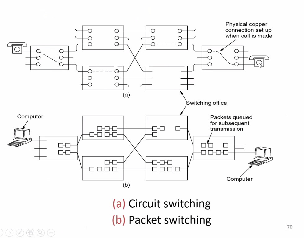
Switching refers to the process of directing and forwarding data packets between devices in a network. It determines the best path for data to travel from the sender to the receiver, ensuring efficient and reliable communication.
(Every block is connected except the upper and lower one)
1. Circuit Switching (7 points)
Connection Type: Connection-Oriented
- A dedicated communication path is established between the sender and receiver before the data transmission begins.
Data Division: No Division (Continuous Stream)
- Data is transmitted as a continuous stream without being divided into smaller units, such as packets.
Path Reservation: Dedicated Path
- Once the connection is established, the entire path from sender to receiver is reserved for the duration of the communication.
Delay: Fixed, Low Delay
- The delay is consistent because the dedicated path is established, ensuring the data flows without interruption.
Efficiency: Depends on Traffic
- Efficient when the data is continuous and constant however, it's inefficient for bursty traffic since the reserved path might remain underutilized during idle times.
Best for real-time communication
Examples:
- Public Switched Telephone Network (PSTN).
2. Packet Switching
Connection Type: Connectionless
- A dedicated communication path is not established between the sender and receiver before the data transmission begins.
Data Division: Data Divided into Packets
- Data is split into smaller units called packets.
Path Reservation: No Reserved Path
- There is no fixed or reserved path for data transmission. Each packet contains its own destination address, and they may take different available routes through the network based on different conditions (e.g., congestion, routing tables).
Delay: Variable Delay
- Since packets travel independently, they may encounter varying delays depending on network conditions, congestion, and routing changes.
Efficiency: High
- Minimizes idle time and ensures efficient bandwidth usage, especially in diverse and large networks.
Ideal for data-centric communication.
Examples:
- The Internet.
3. Message Switching
Connection Type: Store-and-Forward
- A store-and-forward method is used, where the entire message is stored at each intermediate switch before being forwarded to the next hop.
Data Division: Whole Message
- Message switching deals with entire messages, which are forwarded after being fully received and stored by the switch.
Path Reservation: No Reserved Path
- Similar to packet switching, message switching doesn't reserve a dedicated path. However, each switch temporarily stores the entire message until it can be sent to the next switch or final destination.
Delay: High Delay Due to Storage at Each Switch
- There is a significant delay since each message is stored at every intermediate switch. The message is only forwarded once the switch is available, leading to a higher overall delay.
Efficiency: Low Due to Inefficiency in Storing Messages
- The method is inefficient because it requires more memory and processing power to store and forward entire messages. Additionally, it can cause delays and potential bottlenecks at each switch.
Was useful for non-time-sensitive messages.
Examples:
- Telegraph systems or early email systems.
Types of Packet Switching:

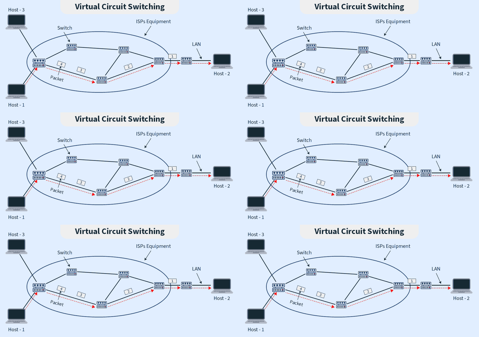
Comparison Table (9 points)
| Feature | Datagram Network | Virtual Circuit Network |
| Definition | A type of packet-switched network where each packet (datagram) is treated independently, and no prior setup is needed before sending data. | A type of packet-switched network where a logical path (virtual circuit) is established between sender and receiver before transmitting data. |
| Connection Setup | No prior setup is required before data transmission. | Requires a connection to be established between the sender and receiver before any data is transmitted. |
| Packet Routing | Each packet is routed independently based on its destination address, and different packets may take different routes. | All packets follow the same logical path established during connection setup, ensuring uniform routing. |
| Order of Arrival | Packets may arrive out of order because they take independent paths and may experience different delays. | Packets arrive in the same order they are sent because they all follow the same predefined path. |
| Reliability | Less reliable as packets may be lost, arrive out of order, or face delays due to independent routing. | More reliable as the predefined path ensures consistent delivery and order. |
| Efficiency | The network can quickly adapt to changing loads by routing packets dynamically and make better use of available bandwidth across all routes. | Once a virtual circuit is established, it reserves resources (e.g., bandwidth, routing paths) for the entire session. This can lead to underutilization if the connection is idle or lightly used. |
| Overhead | Minimal overhead since no connection setup or maintenance is required. | Higher overhead due to the need for connection setup, maintenance, and teardown. |
| Ideal Usecases | Best suited for unpredictable or bursty traffic | More suitable for applications that require a more consistent and reliable connection |
| Examples | Internet browsing | Broadband networks like ATM. |
Differentiate between Network layer and Transport layer. (8 points)
| Network Layer | Transport Layer |
| It is responsible for routing and forwarding packets across networks. | It ensures end-to-end communication reliability between devices. |
| It deals with packets. | It deals with segments (TCP) or datagrams (UDP). |
| Focuses on routing packets from source to destination. | Focuses on delivering data to the correct application. |
| Uses logical addressing (IP addresses) for routing. | Uses port numbers for communication between processes. |
| Provides best-effort delivery, with no guarantee of reliability. | Can ensure reliable delivery (TCP) or offer fast, connectionless communication (UDP). |
| Does not handle flow control or error recovery. | Provides flow control, error detection, and retransmissions (especially in TCP). |
| Connectionless in nature; no established connection for packet delivery. | Can be connection-oriented (TCP) or connectionless (UDP). |
| Key protocols include: IP, ICMP, ARP. | Key protocols inclue: TCP, UDP, SCTP(Stream Control Transmission Protocol). |
Describe key additional features of IPv6 compared to IPv4. Explain the main challenges to implement IPv6 in the existing IPV4 network setup.
IPv6 introduces several enhancements over IPv4 as follows: (9 points)
Larger Address Space: 128-bit addresses provide approximately
3.4×10^38unique addresses.Simplified Header: Streamlined structure reduces processing overhead on routers.
Built-in Security: Mandatory IPSec for encryption and authentication.
Auto-configuration: Stateless address auto configuration (SLAAC) enables devices to self-configure.
Elimination of NAT: Sufficient addresses remove the need for Network Address Translation.
Anycast Addressing: Enables routing to the nearest device sharing the same address.
Improved QoS Support: Flow Label field prioritizes traffic for better Quality of Service.
Support for Larger Payloads: IPv6 supports jumbograms for payloads larger than 65,535 bytes, beneficial for high-bandwidth applications.
Extensibility: Extension headers allow adding features without disrupting the protocol.
Implementing IPv6 in an existing IPv4 network setup comes with several challenges:
Compatibility Issues: Since the two protocols use different address formats and structures, they can't communicate with each other without specialized solutions like dual-stack, tunneling, or translation mechanisms.
Hardware and Software Support: Older networking equipment (routers, firewalls, etc.) and legacy software might not support IPv6. Upgrading or replacing this infrastructure can be costly and time-consuming.
Training and Expertise: Network administrators and engineers may lack experience with IPv6, requiring training to handle its configuration, management, and troubleshooting.
Security Considerations: IPv6 introduces new security challenges. While IPv6 includes built-in security features like IPsec, these need to be correctly configured. Also, the larger address space may make it harder to secure the network.
Network Design Complexity: IPv6 requires changes in the design of networks, especially regarding routing and addressing.
What is IP addressing? How is it classified? How is subnet addressing peroformed? Explain in detail.
IP addressing refers to the assignment of unique identifiers (IP addresses) to devices connected to a network allowing it to communicate with other devices within the same or different networks. These addresses are fundamental to routing and delivering data packets across networks.
IP addresses are classified into two primary versions:
IPv4 (Internet Protocol version 4)
IPv6 (Internet Protocol version 6).
Classification of IP Addressing
1. Based on Address Type
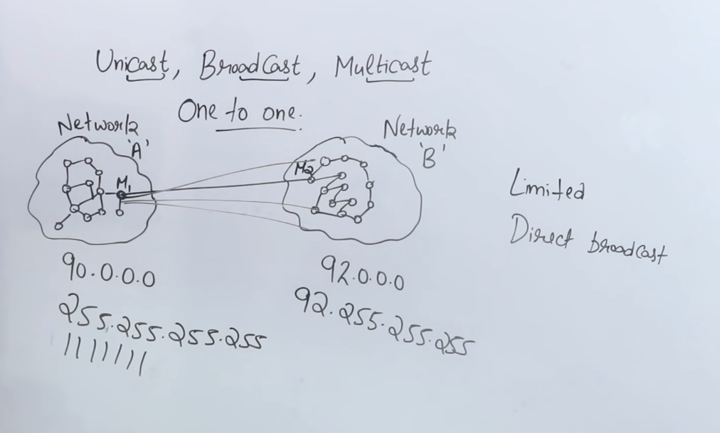
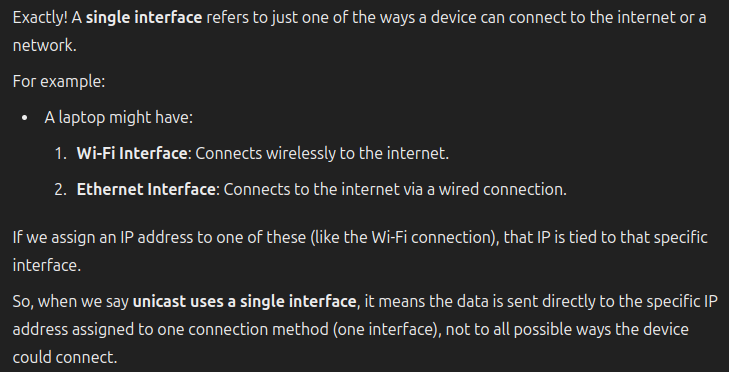
Unicast: An address assigned to a single interface, allowing one-to-one communication.
Broadcast (IPv4 only): An address used to send data to all devices in a network segment.
Multicast: An address assigned to a group of interfaces, enabling one-to-many communication.
2. Based on Address Classes (IPv4) (6 criterias)
IPv4 addresses are divided into five classes based on the first octet. (0-128-192-224-240)
| Class | Range of First Octet | Address range | Default Subnet Mask | Purpose | Example |
| A | 0 - 127 | 0.0.0.0 to 127.255.255.255 | 255.0.0.0 or /8 | For very large networks (large corporations or ISPs) | 10.0.0.01 |
| B | 128 - 191 | 128.0.0.0 to 191.255.255.255 | 255.255.0.0 or /16 | For medium-sized networks (Universities & organizations) | 172.16.0.1 |
| C | 192 - 223 | 192.0.0.0 to 223.255.255.255 | 255.255.255.0 or /24 | Small networks (eg: Small business) | 192.168.1.1 |
| D | 224 - 239 | 224.0.0.0 to 239.255.255.255 | N/A | Used in multicast communications | 224.0.0.1 |
| E | 240 - 255 | 240.0.0.0 to 255.255.255.255 | N/A | Reserved for experimental and future use. | These addresses are not commonly used. |
3. Based on Address Scope
Public IP: Globally unique and routable on the internet.
Private IP: Reserved for use within private networks and not routable on the internet (e.g., 192.168.x.x, 10.x.x.x).
Loopback IP: Reserved for testing purposes on the local device (e.g., 127.0.0.1 in IPv4).
Subnet Addressing
Subnet addressing involves dividing an IP network into smaller sub-networks, or subnets. This process improves network management and security and optimizes the usage of IP addresses. Here’s how subnet addressing is typically performed:
1. Determine the Network and Host Portions
- IP Address Structure: An IPv4 address is divided into two parts: the network portion (identifies the network) and the host portion (identifies the device or host on the network). The default subnet mask determines how the address is split.
2. Choose a Subnet Mask
The subnet mask is used to specify how many bits of the IP address are allocated to the network portion and how many are for the host portion.
A subnet mask like
255.255.255.0(or/24) indicates that the first 24 bits represent the network portion, and the last 8 bits are used for hosts.
3. Decide on the Number of Subnets
The number of subnets is determined by borrowing bits from the host portion of the IP address and using them for the network portion.

4. Calculate the Number of Hosts per Subnet
Once you've borrowed bits for the network, the remaining bits are used for hosts.

5. Apply Subnetting to the Network
Borrow Bits: If, for example, you want to create 4 subnets from a
192.168.1.0/24network, you would borrow 2 bits (because2^2 = 4).New Subnet Mask: By borrowing 2 bits, the new subnet mask would be
255.255.255.192or/26(since 24 + 2 = 26).This new subnet mask allows for 4 subnets, with each subnet having 62 hosts (
2^6 - 2 = 62).
6. Assign Subnet Ranges
Divide the IP range into smaller chunks based on the subnet mask.
(While calculating the range, we have to consider both the addresses as well, for network and the broadcast. In the below ex. we’re adding 64 addresses for each)
For the network
192.168.1.0/26, the subnets would be:Subnet 1:
192.168.1.0to192.168.1.63Subnet 2:
192.168.1.64to192.168.1.127Subnet 3:
192.168.1.128to192.168.1.191Subnet 4:
192.168.1.192to192.168.1.255
7. Consideration of Special Addresses
Network Address: The first address in each subnet, used to identify the subnet.
Broadcast Address: The last address in each subnet, used to send data to all devices in the subnet.
Explain the routing principles and it’s algorithms.
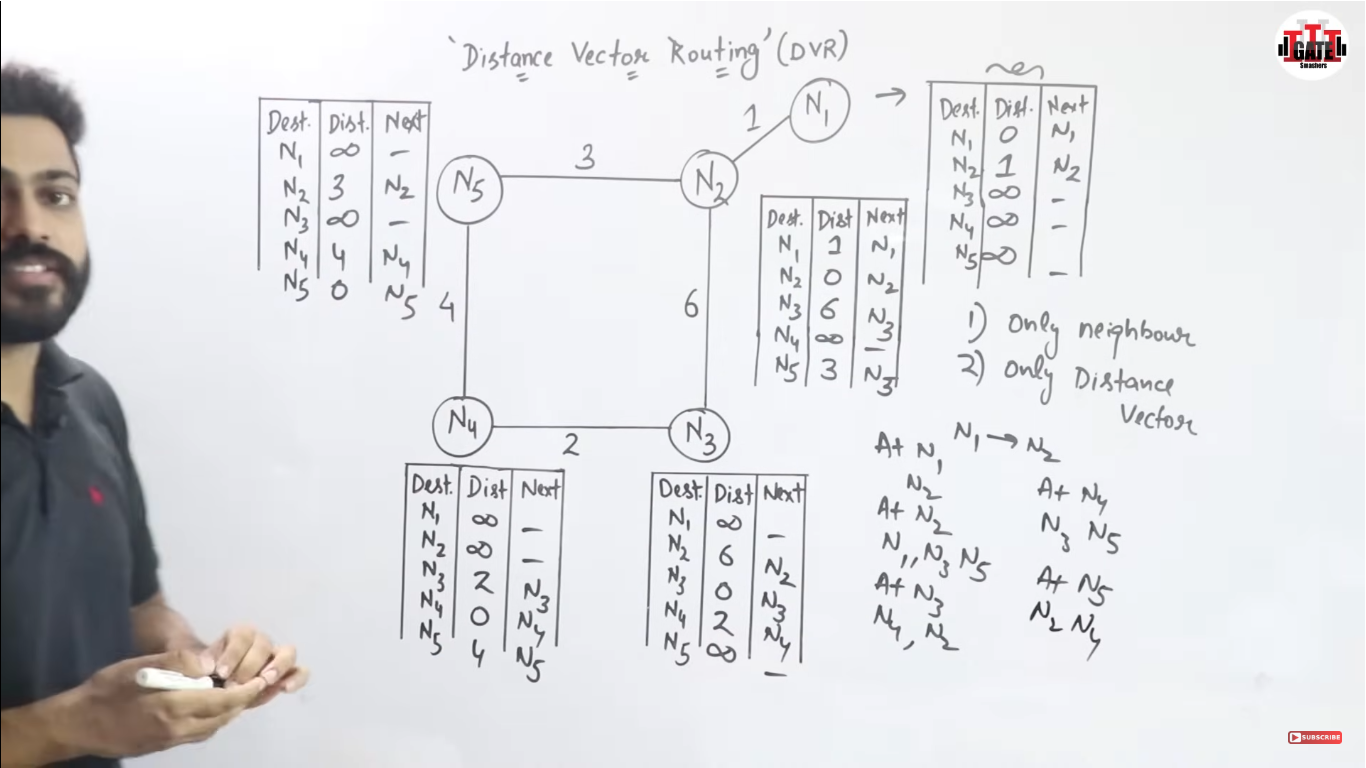
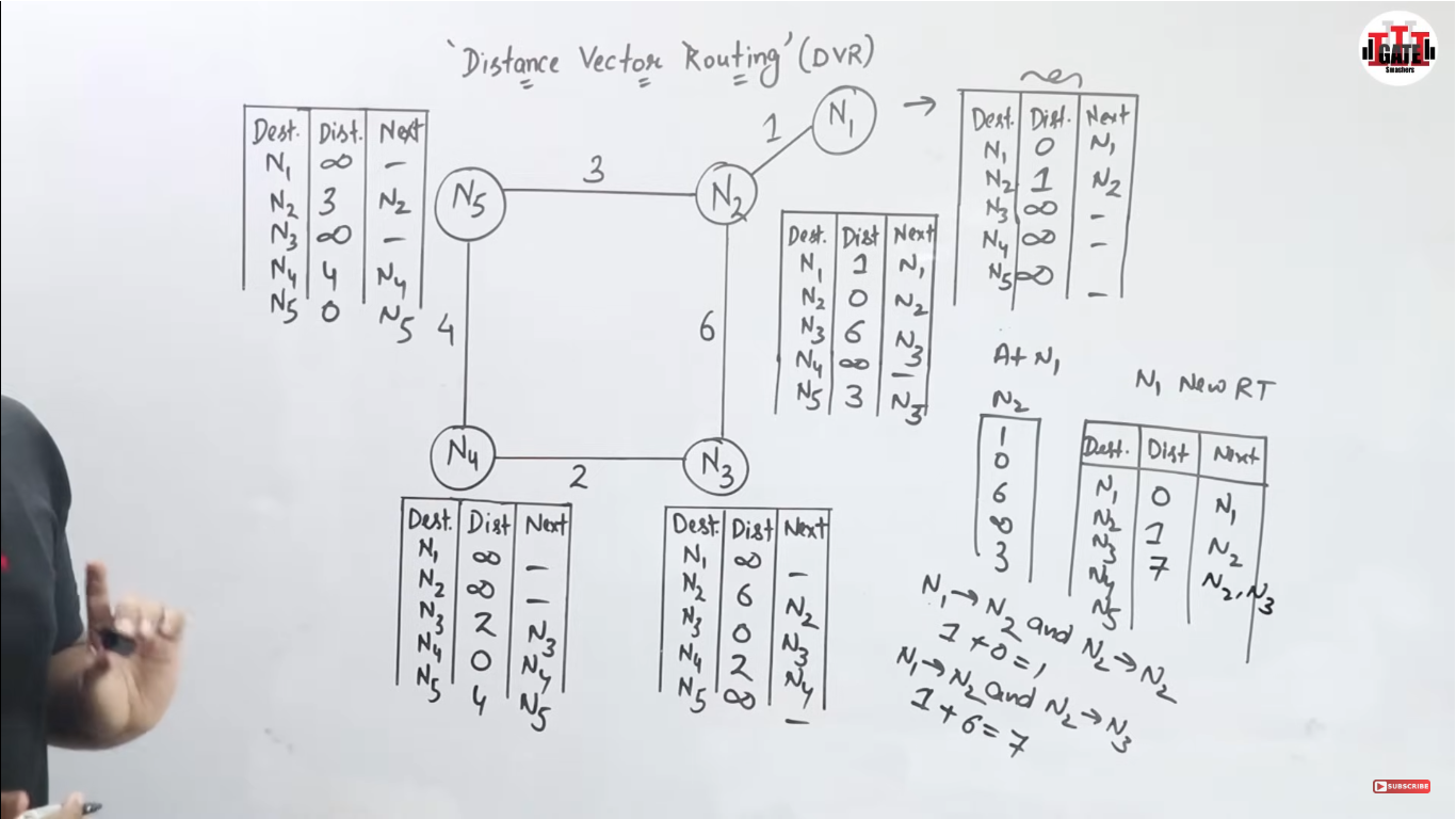
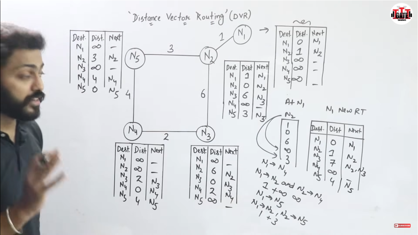
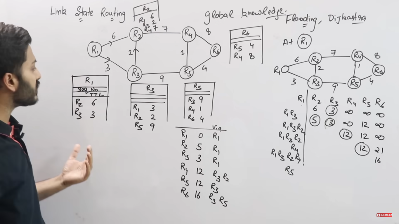
Routing is the process of determining the best path for data to travel from a source to a destination in a computer network.
Key Routing Principles
Path Determination:
Routers analyze network topology to determine the best path for data packets.
Factors like link cost, bandwidth, delay, and hop count influence path selection.
Forwarding:
Once a path is determined, packets are forwarded to the next hop along the route.
Forwarding uses routing tables that map destination addresses to corresponding next-hop routers.
Dynamic vs. Static Routing:
Static Routing: Manually configured routes that do not change unless updated by the administrator.
Dynamic Routing: Automatically adjusts routes based on network changes, such as link failures or congestion.
Convergence:
- Refers to the time taken for all routers in the network to update their routing tables and reach a consistent view after a topology change.
Routing Algorithms
Routing algorithms are categorized into two main types: static and dynamic. Dynamic algorithms are further divided into distance-vector and link-state algorithms.
1. Distance-Vector Routing
Each router maintains a table (vector) of the shortest distances to all known destinations.
Updates are shared periodically with neighboring routers.
Common Protocols:
- RIP (Routing Information Protocol): Uses hop count as a metric, with a maximum of 15 hops to prevent loops.
Key Features:
Simplicity and ease of implementation.
Slower convergence and prone to routing loops (mitigated using split horizon or hold-down timers).
2. Link-State Routing
Each router maintains a complete map (topology) of the network.
Routers broadcast Link-State Advertisements (LSAs) to all routers in the network.
Common Protocols:
- OSPF (Open Shortest Path First): Uses Dijkstra's algorithm for shortest-path computation.
Key Features:
Faster convergence and scalability for large networks.
Higher resource consumption compared to distance-vector algorithms.
3. Hybrid Routing
Combines features of distance-vector and link-state algorithms.
Common Protocols:
- EIGRP (Enhanced Interior Gateway Routing Protocol): Uses both distance-vector and link-state principles for efficiency and reliability.
Define Internet. Differentiate between internet extranet and intranet. (6 points)
The Internet is a global network of interconnected computers that communicate using standardized protocols, such as TCP/IP. It allows users to access, share information, resources, and services across the world. The Internet comprises millions of private, public, academic, business, and government networks.
| Internet | Extranet | Intranet |
| A global network of interconnected computers that communicate using standardized protocols, such as TCP/IP. | A private network granting controlled access to external users, such as business partners. | A private network restricted to internal organizational use. |
| Public and unrestricted access. | Restricted, with access granted to specific external users via credentials. | Restricted to authorized internal users within the organization. |
| Enables global sharing of information and services. | Facilitates secure sharing of business-specific information with external stakeholders. | Enhances internal communication, collaboration, and resource sharing. |
| Used by anyone with an Internet connection. | Used by employees, business partners, vendors, or clients. | Used exclusively by the organization's employees. |
| Less secure due to openness; protected via firewalls, HTTPS, and encryption. | More secure than the Internet; protected by authentication and encryption protocols. | Highly secure; access is limited to internal users and managed via strict organizational policies. |
| Examples include websites, social media, and email services. | Examples include supplier portals and client dashboards. | Examples include HR portals, internal wikis, and knowledge bases. |
Error detection schemes
Error detection ensures the reliable transmission of data across potentially unreliable communication channels by identifying errors introduced during transmission so that the data can be corrected or retransmitted.
Some common error detection techniques:
1. Parity Check
How it works:
A parity bit is added to the data to make the number of 1s either even or odd.
The receiver checks the parity of the received data to detect errors.
Types:
Even Parity: The total number of 1s (including the parity bit) is even.
Odd Parity: The total number of 1s (including the parity bit) is odd.
Limitations: Parity check can only detect single-bit errors and cannot correct them.
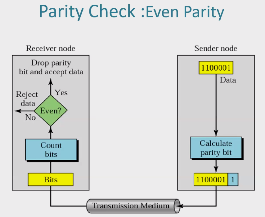
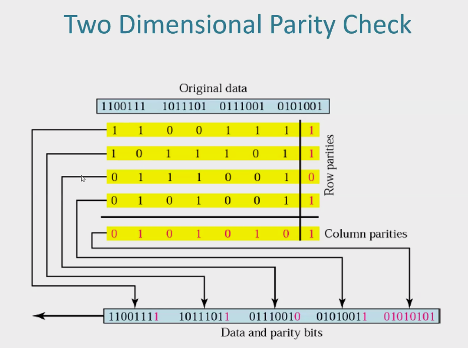
A 2D parity check is an extension of the basic parity check concept that helps detect errors in both horizontal (rows) and vertical (columns) directions in a two-dimensional grid of data.
Diagram for even-parity.
2. Checksum
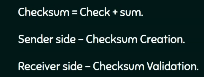
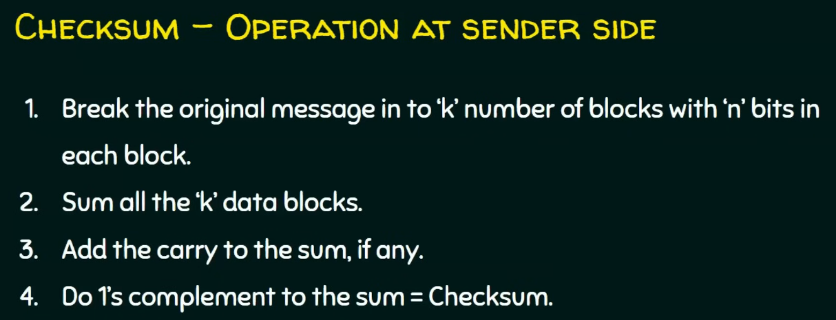
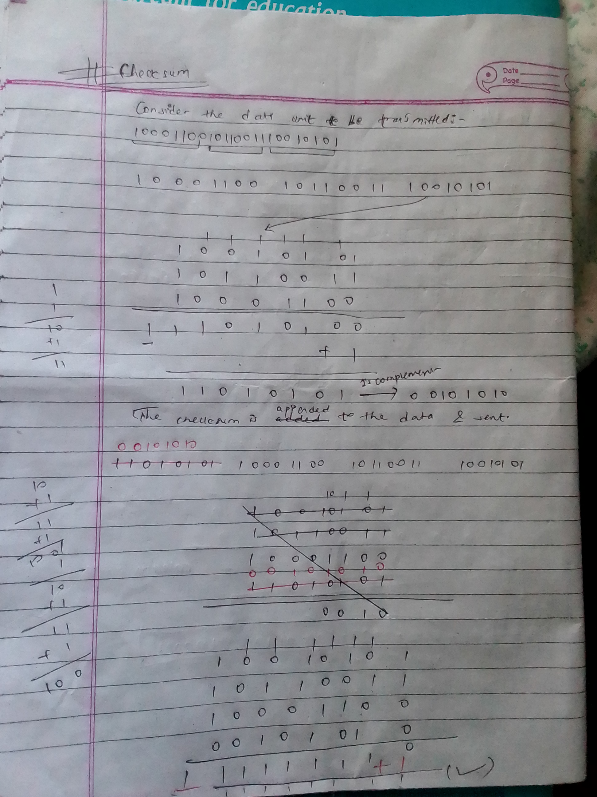
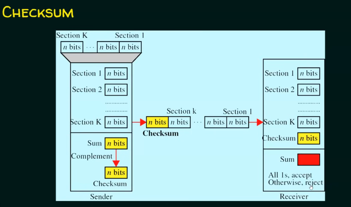
A checksum is an error detection technique used to ensure the integrity of data during transmission or storage. It works by performing a mathematical operation on the data to generate a small, fixed-size value (the checksum). This value is sent along with the data.
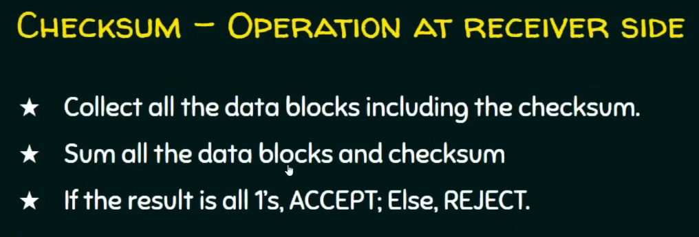
The receiver recalculates the checksum upon receiving the data and compares it with the received checksum value. If they match, it's assumed that the data has been transmitted without errors. (Though we have mentioned compare but I didn’t find it doing)
3. Cyclic Redundancy Check (CRC)
A Cyclic Redundancy Check (CRC) is an error-detecting mechanism.
How it works
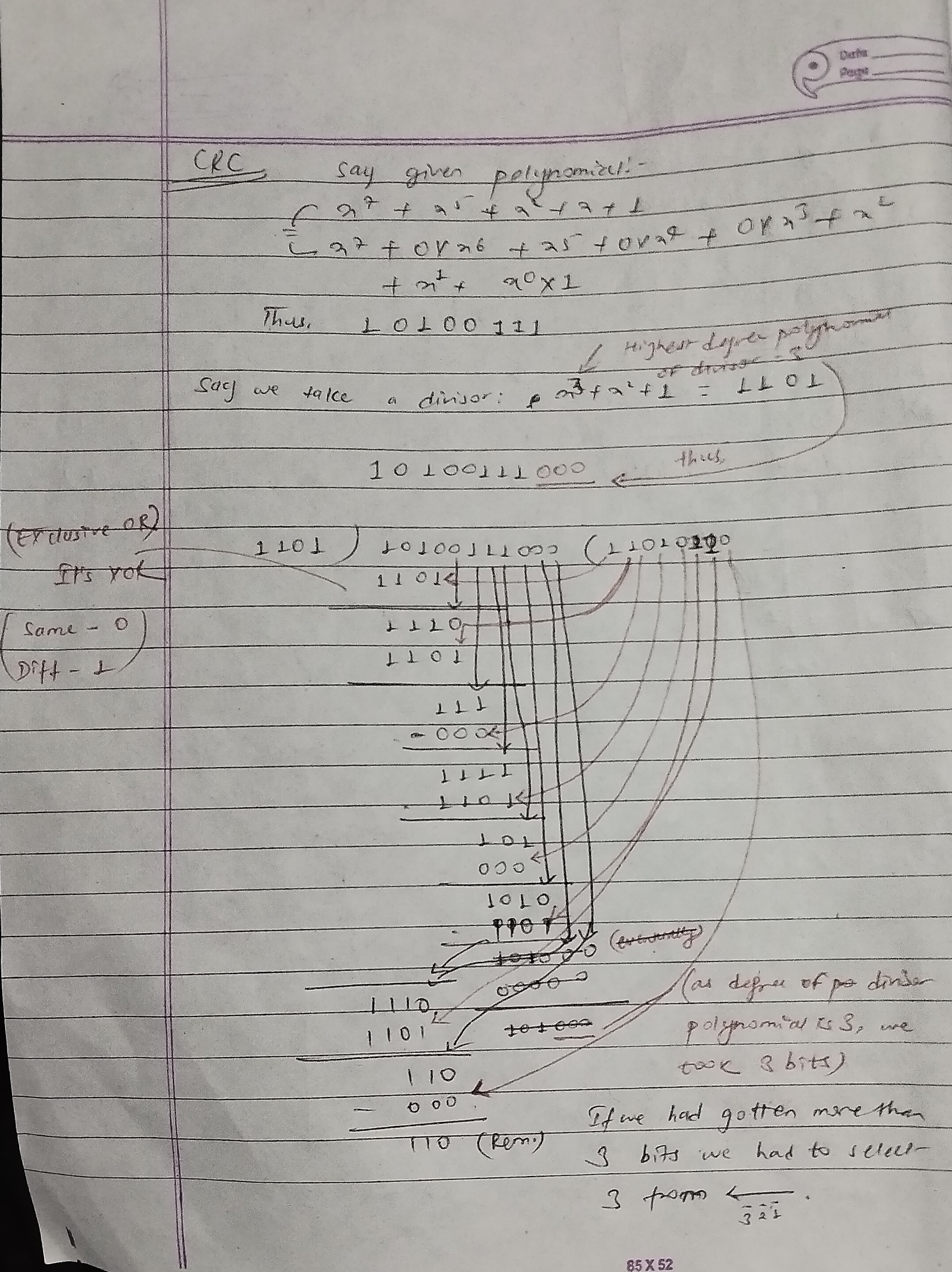
The data to be transmitted is treated as a binary polynomial.
This data polynomial is divided by a predetermined generator polynomial.
The remainder of this division is the CRC.
The CRC is appended to the original data, forming a codeword.
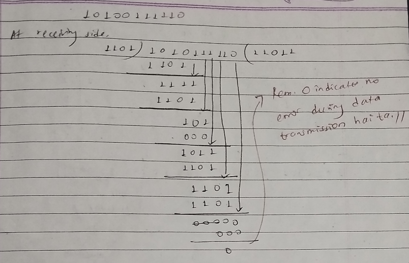
At the receiver/reader, the received data (including the appended CRC) is divided by the same generator polynomial.
If the remainder is zero, it indicates that the data was received without errors. Otherwise, an error is detected.
Dynamic Host Configuration Protocol (DHCP)
DHCP is a network protocol used to automatically assign IP addresses and other network configuration parameters to devices in a network. This ensures that devices can communicate efficiently without the need for manual configuration.
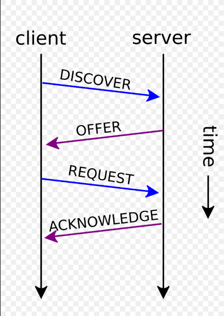
How DHCP Works
DHCP Discovery:
- A client device sends a broadcast message to discover a DHCP server on the network.
DHCP Offer:
- The DHCP server responds with an offer containing an available IP address and other configuration details.
DHCP Request:
- The client sends a request to accept the offered IP address.
DHCP Acknowledgment:
- The server acknowledges the request and assigns the IP address to the client. The client can now use the IP address.
Common Ports
UDP Port 67: Used by the DHCP server to receive client requests.
UDP Port 68: Used by the DHCP client to receive server responses.
Significance of DHCP (7 points)
Automated IP Address Management: Simplifies device setup by dynamically assigning IP addresses without manual intervention.
Efficient Use of IP Addresses: Reuses IP addresses via leasing, optimizing the allocation of limited IPv4 addresses.
Scalability: Supports networks of all sizes, handling thousands of devices with ease.
Seamless Device Connectivity: Ensures mobile and roaming devices connect effortlessly to different networks.
Centralized Network Configuration: Provides consistent settings for IP addresses, gateways, DNS servers, and more.
Reduced Administrative Overhead: Minimizes human errors and reduces the workload for IT teams.
Critical for Dynamic Networks: Powers modern cloud environments, IoT ecosystems, and virtualized infrastructures.
DNS Name Resolution
DNS name resolution is the process of translating a human-readable domain name (e.g., www.example.com) into its corresponding IP address (e.g., 192.0.2.1) so that network devices can locate and communicate with the server.
Here's how it works step by step:
1. User Enters Domain Name
- The user types a domain name into a browser, such as
www.example.com.
2. Browser Cache Check
The browser checks its cache to see if it already has the IP address for the domain.
If found, the process stops here.
3. Operating System Cache
If the browser cache misses, the request is forwarded to the operating system's DNS resolver.
The OS checks its cache for the IP address.
4. Query to Recursive Resolver
- If the OS cache misses, the query is sent to the configured DNS resolver, often provided by the ISP or a public DNS service like Google DNS (8.8.8.8).
5. Recursive Resolver Query Process
The resolver attempts to resolve the domain name by querying various DNS servers in a hierarchical manner:
a. Root DNS Servers
The resolver queries a root DNS server for the top-level domain (TLD), such as
.com.The root server responds with a referral to the appropriate TLD nameserver.
b. TLD Nameservers
The resolver queries the TLD nameserver (e.g.,
.comnameserver) for the domain.The TLD server responds with a referral to the authoritative nameserver for the specific domain.
c. Authoritative Nameservers
The resolver queries the authoritative nameserver for the domain (e.g.,
example.com).The authoritative nameserver responds with the IP address of the requested domain.
6. Response to Resolver
- The recursive resolver receives the IP address and caches it for future queries.
7. Response to User
- The resolver sends the IP address back to the user's browser.
8. Browser Connects to Server
- The browser uses the IP address to establish a connection with the web server.
9. Website Loading
- The browser sends an HTTP/HTTPS request to the server, retrieves the website content, and displays it to the user.
This hierarchical process ensures the DNS system is scalable and efficient. Caching at various levels (browser, OS, and resolver) minimizes the need for repetitive queries, improving performance.
What are the advantages of using UDP over TCP? (6 points)
Here are the advantages of UDP over TCP:
Lower Latency: UDP does not establish a connection, making it faster for time-sensitive transmissions.
Lightweight: UDP has less overhead because it does not include features like error correction, acknowledgment, or retransmission.
Broadcast/Multicast Support: UDP allows broadcasting and multicasting, enabling the delivery of data to multiple recipients simultaneously.
Stateless Communication: UDP does not maintain a session, reducing resource usage on both sender and receiver sides.
Resilience to Packet Loss: Applications like voice-over-IP (VoIP) or live video streaming can tolerate some packet loss without impacting the user experience.
Supports Custom Protocols: Provides flexibility to build custom error-checking or retransmission mechanisms tailored to specific application needs.
CSMA/CD: Carrier Sense Multiple Access with Collision Detection
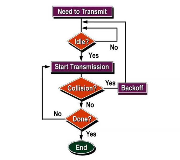
CSMA/CD is a media access control (MAC) protocol commonly used in Ethernet networks. It's a method for multiple devices to share a single communication channel without causing excessive collisions.
Working Principle:
Carrier Sense: Before transmitting, a device "listens" to the channel to detect if it's idle or busy. If busy, the device waits until the channel becomes idle.
Transmission: Once the channel is idle, the device starts transmitting its data.
Collision Detection: While transmitting, the device continues to "listen" to the channel. If it detects another device transmitting (collision), it immediately stops transmitting.
Backoff: After a collision, the device waits for a random amount of time before attempting to retransmit. This random wait helps to avoid immediate re-collisions.
Retransmission: After the random wait, the device again listens to the channel and repeats the process.
Diagram:
Redundancy decreases the speed of communication, but is required for error detection and correction. Explain.
The statement "Redundancy decreases the speed of communication, but is required for error detection and correction" highlights a fundamental trade-off in computer networks and data communication systems.
Redundancy refers to the addition of extra bits or data to the original message to help detect or correct errors that may occur during transmission. While redundancy increases the reliability of communication, it also reduces the effective data rate (speed) because more bits are transmitted than necessary.
1. Error Detection: Parity Check
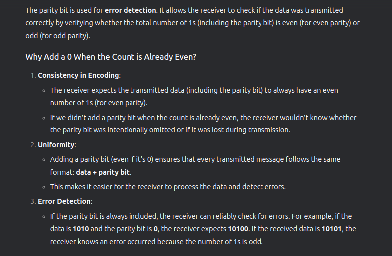
Parity Check
How it works:
A parity bit is added to the data to make the total number of 1s either even (even parity) or odd (odd parity).
The receiver checks the parity of the received data to detect errors.
Example: Even Parity Check
Original Data: 1011
Redundancy: Add a parity bit to make the total number of 1s even.
Number of 1s in 1011: 3 (odd)
Parity bit = 1 (to make the total number of 1s even)
Transmitted Data: 1011 1
Transmission and Error Detection
If the transmitted data is 10111 and no error occurs, the receiver checks the parity:
Number of 1s: 4 (even) → No error detected.
Drop the partity bit and accept data.
If an error occurs during transmission (e.g., the data becomes 10011):
Number of 1s: 3 (odd) → Error detected.
Reject Data.
Limitation of Error Detection
- The parity check can detect single-bit errors but cannot correct them.
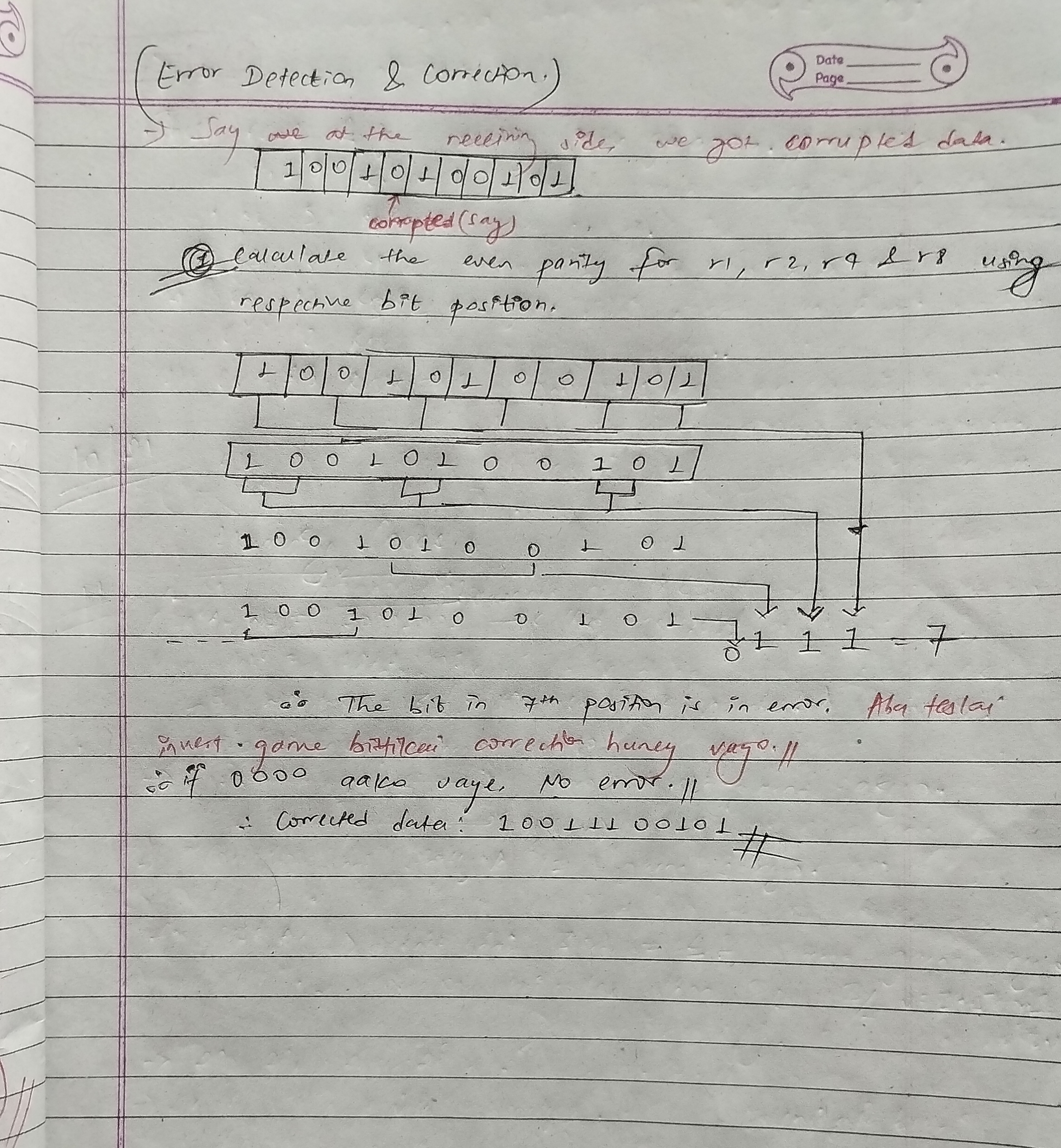
Error Correction: Hamming Code
How it works:
Multiple redundant bits are added to the data to create a Hamming code.
These bits are placed at specific positions (powers of 2) and are used to detect and correct errors.
Example:

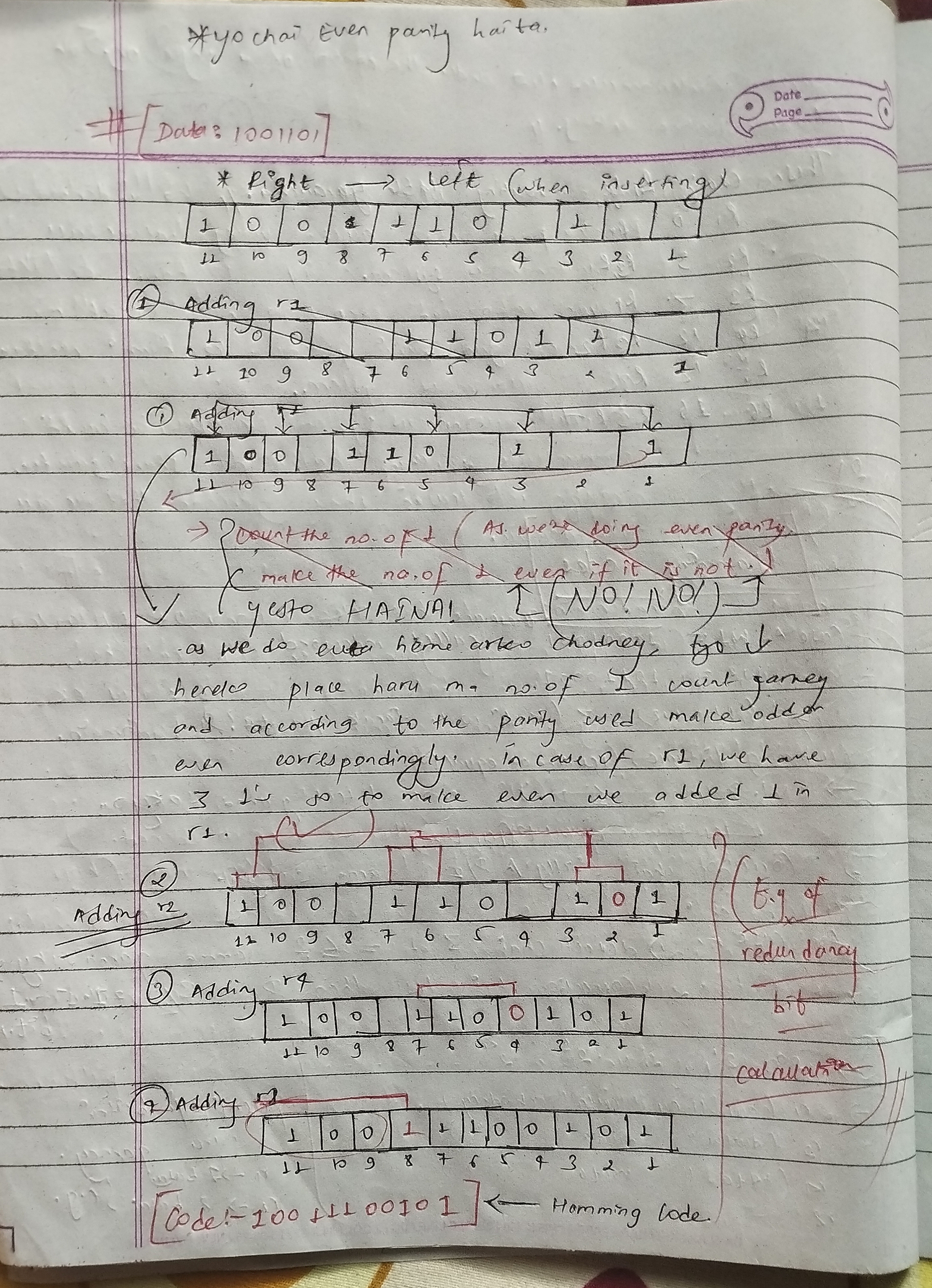
Advantage:
- Hamming code can detect and correct single-bit errors.
Computer Firewall
A computer firewall is a network security system designed to monitor, filter, and control incoming and outgoing network traffic based on predefined security rules.
Key Features of Firewalls:
Traffic Filtering: Blocks or allows data packets based on IP addresses, ports, or protocols.
Access Control: Restricts unauthorized users or devices from accessing the network.
Threat Prevention: Protects against malware, hackers, and other cyber threats.
Network Segmentation: Divides networks into smaller segments to limit the spread of attacks.
Logging and Monitoring: Tracks network activity for analysis and auditing.
Types of Firewalls:
Hardware Firewall: A physical device that protects an entire network (e.g., routers with built-in firewalls).
Software Firewall: Installed on individual devices to control traffic to and from that device.
Packet-Filtering Firewall: Examines packets and allows or blocks them based on rules.
Stateful Inspection Firewall: Tracks the state of active connections and makes decisions based on context.
Proxy Firewall: Acts as an intermediary between users and the internet, filtering traffic at the application layer.
Next-Generation Firewall (NGFW): Combines traditional firewall features with advanced capabilities like intrusion prevention and deep packet inspection.
Limitations:
Cannot protect against internal threats.
May slow down network performance if not configured properly.
Requires regular updates to remain effective.